Sampler Modulation
Modulation
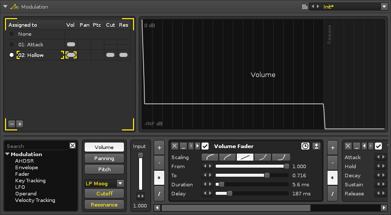
Adding modulation to samples greatly expands the possibilities of their sound beyond the original audio. To achieve this, various devices are chained together to create a modulation envelope. Separate envelopes are used to affect five basic properties of a sample: Volume, Panning, Pitch, and the Cutoff and Resonance of an added filter. These five envelopes are collected together as a Set. Any number of Sets can be created and each instrument has its own unique Set list.
The individual samples of an instrument can be assigned any one of its Sets, allowing different samples be affected by modulation in different ways. A Set can also be assigned to multiple samples simultaneously and any changes made to a Set will affect all linked samples.
Modulated samples are processed polyphonically (each instance of a sound is generated independently).
The interface is split into three sections. At the upper-left is the Set list Load & Save and the large section to right graphically shows the results of the device chain. The lower section contains the properties selector and device chain.
Creating Modulation Sets
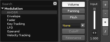
The bottom section of the Modulation interface is dedicated to the creation of envelopes for the five basic properties of a modulation Set: Volume, Panning, Pitch, and the Cutoff and Resonance of an added filter (they will be unavailable until a filter is chosen from the drop-down menu).
Each property has its own Input slider, which is used to adjust the starting value of the envelope. The envelope is constructed by inserting modulation devices and creating a chain. To add a device from the list, either double-click on it or drag and drop it into the chain at the desired position.
Immediately before every device are a set of four buttons for the mathematical operations: Add, Subract, Multiply and Divide. These change how the envelope will be altered by that device.
Modulation Devices
Note that the name of a device will reflect the modulation property that it is affecting.
Common Effect Layout and Controls
Each effect that you add to the chain has a standard set of buttons to perform common functions:
 - Remove the device from the chain.
- File:3.0 device-minimize.png - Minimize the device.
 - Move device to left/right. Right-click to move to start/end of chain.
 - Enable/disable device.
 - Toggle sync to milliseconds/beats. Not present on all devices.
 - Toggle bipolar (positive and negative values)/unipolar (only positive).
AHDSR
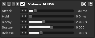
- Attack:
- Hold:
- Decay:
- Sustain:
- Release:
Envelope
- Point Controls:
- Time:
- Value:
- Curve:
- Length:
- Ext. Editor:
- Loop:
- Sustain:
- Release:
- Presets:
Fader
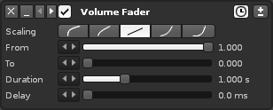
- Scaling:
- From:
- To:
- Duration:
- Delay:
Key Tracking
The Key-Tracker device works in much the same way as the Velocity Tracker, except it adjusts a parameter according to note value instead of velocity.
- Min: Minimum note range that will be used for input.
- Min: Maximum note range that will be used for input.
LFO
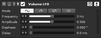
The LFO device allows you to easily create a constantly looping Automation. Any effect parameters can be modulated this way, even those of plugin effects or instruments which cannot normally be modulated within the plugin itself.
- Mode:
- File:Vvoois renoise lfo sine.png - Sine wave oscillator.
- File:Vvoois renoise lfo saw.png - Sawtooth oscillator.
- File:Vvoois renoise lfo pulse.png - Pulse oscillator.
- File:Vvoois renoise lfo random.png - Random oscillator.
- Frequency: The speed of the modulation in Lines per Cycle. For example, an LPC of eight will cycle the LFO once every eight pattern lines.
- Amplitude: The maximum range that will be applied to the destination parameter. 100% will modulate the full range.
- Dephase:
- Delay:
Operand
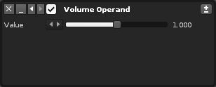
A simple value input device. The "Input" slider at the beginning of the chain is also an Operand device.
- Value: The value which will alter the envelope.
Velocity Tracking
Velocity Tracking adds another dimension of control by responding to the velocity values of notes. For example, when modulating a Filter's cutoff value with a Velocity device, the sound of an instrument can then be drastically altered by pressing the keys harder or softer.
- Mode: Clamp: Each note within the range will trigger an event, while notes outside of the range will be clamped to the specified limits. Scaling: The scaling that will be applied from the input to the destination. By default, the input will be mapped linearly, but you can also select from two exponential and two logarithmic scales.
- Min: The minimum value to be used from the destination parameter's range.
- Max: The maximum value to be used from the destination parameter's range.
